Transitioning FLOEFD Projects Across Different CAD Platforms
Transitioning FLOEFD Projects Across Different CAD Platform
Simcenter FLOEFD is a CFD tool that works directly inside CAD software like Solidworks (Standalone revision), Siemens NX, Solid Edge, CATIA, and Creo. This makes it easy for engineers to analyze thermal and fluid behavior in the CAD environment they're familiar with.
When you need to move a FLOEFD analysis from one CAD system to another (e.g., from NX to SolidWorks), you can use the Project Template feature.
Basic Principle
FloEFD is an add-on tool for CAD systems, allowing you to "link" thermal properties like heat sources, boundary conditions, material properties, mesh settings, and goals to various CAD objects. This setup establishes a connection between FloEFD settings and CAD components.
Here's how it works with the provided diagram:
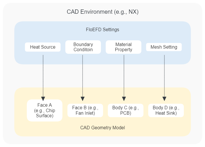
- CAD Environment: This is where your CAD models are created and managed, such as NX.
- FloEFD Settings: These include configurations like heat sources, boundary conditions, material properties, and mesh settings that are applied to the CAD model.
- CAD Geometry Model: This represents the physical components of your design, like a chip surface (Face A), fan inlet (Face B), PCB (Body C), and heat sink (Body D).
FloEFD settings are applied to specific parts of the CAD model, creating a direct link between the simulation parameters and the geometry.
To transfer these settings across different CAD platforms, FloEFD uses a Project Template. This template exports all the predefined thermal properties from one CAD system and can be imported into another. Once imported, you simply re-link these properties to the corresponding parts in the new CAD system.
The Project Template is version-independent, meaning it can be used across different versions of FloEFD without compatibility issues. This makes it a powerful tool for maintaining consistency in thermal and fluid analysis across various CAD environments.
The key is the Project Template file (*.fwp). This file saves all your analysis settings (like boundary conditions and mesh details) but doesn't include the CAD geometry itself.
Simple Steps to Move the Project
-
Create the Template:
- In the original CAD system, open your FLOEFD project.
- Right-click the project name in the FLOEFD tree and select “Create Template.”
- This creates a
*.fwpfile with all your settings.
-
Copy the Template File:
- Find the
*.fwpfile (usually in the directory shown under Options > General Options > Directory for project template). - Copy this file to a place where the new CAD system can access it.
- Find the
-
Prepare the Geometry:
- In the new CAD system, open the CAD model you want to analyze.
-
Apply the Template:
- Create a new FLOEFD project on the new CAD model using the copied
*.fwpfile. - Now, the new project has all the settings from the original analysis.
- Create a new FLOEFD project on the new CAD model using the copied
Important Final Step: Fix Lost References
After applying the template, the settings will be there, but they won’t be linked to the new CAD model’s geometry. You need to fix this:
-
Find Broken Links:
- Look for warning icons in the FLOEFD Project Tree. These show features (like boundary conditions or goals) that lost their links to the geometry.
-
Re-link Geometry:
- Manually edit each feature and re-select the correct faces or surfaces on the new CAD model. This fixes links for:
- Boundary conditions (inlets, outlets, walls)
- Goals/sensors (points or surfaces for monitoring)
- Local mesh regions
- Manually edit each feature and re-select the correct faces or surfaces on the new CAD model. This fixes links for:
-
Check Everything:
- Use the “Check Geometry” and “Computational Domain” tools to make sure the new model’s fluid and solid regions are correctly defined.
By updating these lost references, you can easily move your FLOEFD analysis to a new CAD system without redoing everything.